 |
| |
| A. Base Jack and Universal Jack |
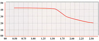
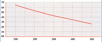
The 57 kN capacity galvanized jack has an adjustment range of over 45 cm. It is manufactured from 38 mm outside diameter steel tubes with a rolled/cut thread. The jack can be used either at top or the bottom of the vertical (standard), so the reasonable portion of the jack will always remain inside the vertical for safety. The figure below illustrates the safe working load on tubular Jacks. The data incorporates factors of safety on failure of 2.75. |
| |
 |
| |
|
| |
| Horizontals (Ledgers) |
| |
| HORIZONTALS (S.W.L) |
| CODE |
HEIGHT (A) (m) |
APPROX
WEIGHT (kg) |
TWO EQUALLY SPACED POINT LOAD (kN) |
| CSFH171 |
1.71 |
2.70 |
1.29 (Each) |
| CSFH340 |
3.40 |
- |
- |
| CSFH352 |
3.52 |
- |
- |
| CSFH370 |
3.70 |
- |
- |
| CSFH480 |
4.80 |
- |
- |
|
| Note: The above S.W.L. incorporate safety factor of 2.0. |
| |
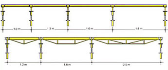
| Grids Loads |
| HORIZONTALS (S.W.L) |
DECKING BEAM
SIZE (m) |
LEDGER
SIZE (m) |
AREA
(m2) |
| MAX. SLAB THICKNESS (cm) LIVE LOAD = 200 kg/m2 |
| SOLID SLAB |
HOLLOW SLAB |
|
| CSFGL18 |
1.8 |
4.50 |
27.5 |
34.4 |
| CSFGL13 |
1.3 |
4.00 |
32.0 |
40.0 |
| CSFGL13 |
1.3 |
3.25 |
41.2 |
51.5 |
| CSFGL18 |
1.8 |
3.24 |
41.4 |
51.7 |
| CSFGL12 |
1.2 |
3.00 |
45.3 |
56.7 |
| CSFGL16 |
1.6 |
2.88 |
47.5 |
59.4 |
| CSFGL11 |
1.1 |
2.75 |
50.2 |
62.7 |
| CSFGL10 |
1.0 |
2.50 |
56.0 |
70.0 |
| CSFH13 |
1.3 |
2.34 |
60.4 |
75.5 |
| CSFH09 |
0.9 |
2.25 |
63.1 |
78.9 |
| CSFGL12 |
1.2 |
2.16 |
66.1 |
82.6 |
| CSFGL18 |
1.8 |
2.16 |
66.1 |
82.6 |
| CSFGL08 |
0.8 |
2.00 |
72.0 |
90.0 |
| CSFGL11 |
1.1 |
1.98 |
72.8 |
91.0 |
| CSFGL16 |
1.6 |
1.92 |
75.3 |
94.2 |
| CSFGL10 |
1.0 |
1.80 |
80.9 |
101.1 |
| CSFGL09 |
0.9 |
1.62 |
90.8 |
113.4 |
| CSFGL13 |
1.3 |
1.55 |
94.6 |
118.2 |
| CSFGL06 |
0.6 |
1.50 |
98.7 |
123.3 |
| CSFGL08 |
0.8 |
1.44 |
103.1 |
128.9 |
| CSFGL12 |
1.2 |
1.44 |
103.1 |
128.9 |
| CSFGL11 |
1.1 |
1.32 |
113.2 |
141.5 |
| CSFGL10 |
1.0 |
1.20 |
125.3 |
156.7 |
| CSFGL06 |
0.6 |
1.08 |
140.1 |
175.2 |
| CSFGL09 |
0.9 |
1.08 |
140.1 |
175.2 |
| CSFGL08 |
0.8 |
0.95 |
158.7 |
198.3 |
| CSFGL06 |
0.6 |
0.72 |
214.2 |
267.8 |
|
Concrete Unit Weight (Solid) = 2500 kg/m3 |
Concrete Unit Weight (Hollow) = 2500 kg/m3 |
|
| |
 |
| |
|
| |
| Early Striking Technique |
Concrete usually takes about a month to achieve its designed strength after casting. This is why the complete support cannot usually be removed until about half this time has passed (depending on temperature and cube strenght tests).
However, early striking is a technique which involves the form work being removed 3 or 4 days after pouring, leaving only the supporting scaffolding or drops until the concrete has the strength to support itself.
When you consider the high cost of form work these days, it is easy to see how traditional form work which involves leaving the full structure in place for two weeks is now outdated. With the accelerated cycle the new system gives the same equipment can be used sooner, thus being more economical. In other parts of the world where labour and equipment are expensive, this economical, safe and efficient system has been in operation for over fifteen years. |
| |
| Erection & Dismantling and Dismanntiling Procedures |
| A. Erection Procedure |
| |
|
 |
Place adjustable base jacks at even intervals on ground. |
| |
|
|
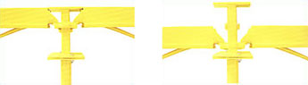
Put a standard onto a base jack and place two ledgers in its lower cup. The ledgers should form a 90o angle. Place the upper cup of the standard over the two blade ends. Do not tighten. |
| |
|
|
Put a second standard on another base jack with the perviously assembled ledger. Fix its blade end into the cup of this standard. Follow the same procedure for the third time to form a right angle. |
| |
|
|
Complete rectangle with a fourth standard and another two ledgers. Add four ledgers to the top. Now tighten the structure fully. |
| |
|
|
Assemble two braces diagonally and add the universal jacks and drophead on the top of the completed supporting grid. |
| |
|
|
Add the decking beams and infill beams. Tighten joints. |
|
| |
To assemble CSF Systems Scaffolding, remove the drophead from the universal jack at one end, and attach it to the beam. The finished beam completed with drophead can be raised and lowerd over the jack. |
| |
 |
| |
|
| |
| Dismantling Procedures |
Whether the early striking technique is followed or not, the procedure for dismantling is the same.
Decking beams and infill beams can be dismantled by striking the drophead wedge. This striking causes the beams to drop only about 115mm, which gives enough clearance for removing the infill beams.
After striking the drophead wedge the decking and infill beams can be taken away as the concrete soffit is supported and left untouched during the curing period. The beams can then be re-used for another concrete structure, needing only another set of supporting components.
Complete safety in the dismmantling procedure is ensured because decking beams and infill beams cannot fall because after striking must be removed manually. |